Bracing System – Structural arrangement that ensures stability in Longitudinal Direction

What happens to a building when it is subjected to wind loads?

Any building or structures, in general, must ensure stability in two directions (Lateral & Longitudinal) to safely transfer loads from the location of application to the ground.

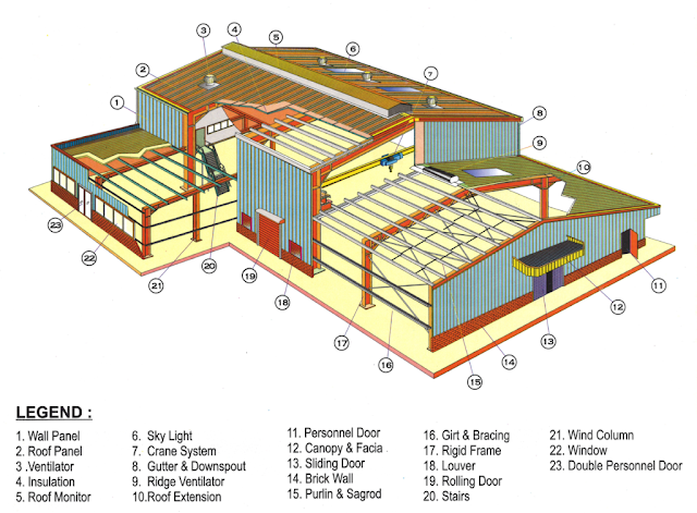
Considering a typical steel warehouse building something similar to the following image, when it is subjected to wind load along the lateral direction, stability is ensured by the portal frame action.

Lateral Direction – Along width of the building

Longitudinal Direction – Along Length of the building

PEB building with legends marked, structures simplified


The column and the rafter connected using a rigid joint act as a portal to sustain the lateral loads that act on the building.

So, the building is fine in the lateral direction. What if the wind blows in the longitudinal direction? 

How longitudinal force gets transferred through the system?

In the longitudinal direction, when the force acts on the gable ends of the building, the first component to interact with the load is the cladding materials (Sheeting). Through which the force gets transferred to the next component, Girts. Obviously, we would have designed this member to withstand the wind force, so that member will be strong enough to take the load and transfer it to the supporting member. 

Girts are in turn connected to wind columns. Now, the load reaches the wind column. This is where it gets interesting.

Mostly the wind columns will be pinned supported at the base as well as at the top (at rafter location). When wind load acts on these columns, there will be reactions at the ends (top and bottom) of the column. At the bottom end, the force is transferred to the ground as shear through anchor rods.

There arises a question.
What happens at the top? 
Whether we have to design the gable end frames with these wind reactions acting in a longitudinal direction?
 
No need. Actually, the reaction force which generates at the top of the wind column gets transferred through the strut tubes or purlins that we provide behind every wind column location.
 
And there arises another question.
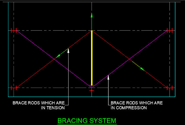
If the strut tubes carry the load from the wind column, then what is the role of providing bracing?
The actual purpose of the strut tube is to transfer the force from the gable end frame to the interior frames. But in order to transfer the force to the ground, we need a bracing system
 
The most commonly used bracing system in a steel building is “Diagonal Rod Bracing” (X-type bracing).
How does Diagonal Rod bracing behave for the longitudinal load? 
Once the force gets transferred to the bracing location, the brace rods won’t let the force to continuously flow through the frames. Usually, in the diagonal rod bracing, one set of bracing rods will be tension and the others will be in compression. When the longitudinal load reaches the braced bay, the rod which is in compression buckles away and does not carry any force since it is slender. The other set of rods that are in tension will be active in carrying the force. A certain amount of lateral force will be absorbed by the bracing. These forces are transferred from the bracing system at the roof to the wall and get transferred to the ground as a shear force through anchor rods. (See below figure)
 
diagonal rod bracing system


Note that, while providing diagonal rod bracing, only one set (rods in tension) of rods will be in action on transferring the force. So, you can ask me why we are providing two diagonals then?
 
The answer is so simple when the direction of force got reversed, the other set of diagonal members will be the one that transfers the force to the ground. That’s the reason why we are provide bracing in a pattern of X.
 
Since, these rods carry the longitudinal force through the tension action, while designing they have to be considered as a “Tension Only Members”
What do we do, if we go for the Diagonal Angle or Tubular section as our bracing members?
If we are adopting Angle or Tubular sections as the bracing members. We should be aware that they are capable of transferring loads through compression as well as tension. So, the entire load transferring mechanism differs.Both the set of bracing members will be in action transferring the force. In that case, it is advisable to design those bracing members as a “Truss Members”.

The provision of Rod, Angles, or Tubular sections as the bracing member depends on the magnitude of the lateral force that is acting on the building. One must calculate the lateral force that is intended to act on a structure and choose the bracing member accordingly.
 
Moving further, there arises the next question.
How many braced bays are required for a building?
Let’s look into this question with an example.
 
Consider a building whose length is around 64 m and we are dividing it to 8 nos. of 8m bay spacing. The minimum number of braced bays to be provided in this case is 3. You might wonder, from where did that magical number 3 came from..? Actually as per IS 800–2007, the maximum center to center distance between braced bay is 40 m. That means you cant go beyond 40 m, without providing a braced bay and which leaves us with 3 braced bays.
 
Also check out my YouTube Channel: Structures Simplified

Leave a Reply

Your email address will not be published. Required fields are marked *