
If we consider ourselves attending a design class in the undergraduate degree program, once the design philosophies are over, the first design lecture would be on “Design of Tension Members”.
Have you ever wondered, why we are learning this thing first?
You can check any standard textbooks, once the author finished talking about introductions, prerequisites, design philosophies, the first actual design would be “Design of Tension Members”. In fact, if you check the codebooks, they too follow the same order.
To answer the question, WHY?
It is the simplest design involving not so complicated loading conditions and very few limit-states that are easy to understand.
To elaborate, it is easy to calculate the stress component in the case of tensile loading (Stress=Load/Cross-sectional Area), which is not so with transverse loading, since we need to calculate bending stresses.
To gain some insight regarding stresses and forces and why we calculate stress, read this article – Why do we calculate STRESS, when we have FORCES?
Regarding the limit states for tension members, the tension member can fail due to
- Gross section yielding
- Rupture of Net section
Kindly note, I have not listed the limit states for the failure of connections.
See, it is simple. Very few concepts and that is why it is placed first in the order.
Before moving to the topic, would like to ask one more question. What are the most widely used tension member sections?
As a designer, say, I am about to design a tension bracing member, the first section that comes to my mind would-be “Angle Sections” (Hoping, you too think of the same).
When considering angle members, there is one important behavior or phenomenon which should be addressed or taken into account while determining its tensile capacity. It is nothing but “Shear Lag”, which is the main concentration for today’s article.
Contents
- What is meant by “Shear Lag effect”?
- Exercise to feel shear lag
- How do we incorporate “Shear Lag” in the calculation of tension capacity?
- As per AISC-360-10
- As per IS-800:2007
- Inference/Conclusion
What is meant by “Shear Lag effect”?
The attached image shows the gusset plate connection of typical bracing members.
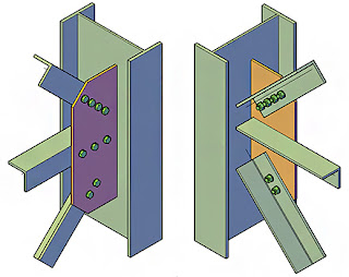
The most important thing to notice is the way in which they are connected. As we can clearly see, they are connected using bolts to the gusset plate, which in turn is welded to the main member.
What is so special about this?
“Only one of the leg is connected”. So what?
You can say, that if the bolts are properly designed to take care of the design force, then the connection should work fine.
The problem is not with the connection, it is with the behavior of the member. Since only one leg is connected, the entire tensile force will get transferred to that leg, to flow through the connection. Which totally cancels out our limit state checks for the tension member.
We will be calculating yielding strength based on the entire area of the member (including both the legs) and rupture strength based on the net area (including both legs neglecting the bolt hole). Since at the location of connection, all the forces are getting transferred to the connected leg, the area of concentration of force reduces, so both of these limit states are not valid.
Usually, the force which is acting in one of the legs gets transferred to the entire cross-section in the form of shear. At the location of the connection, the stress distribution is non-uniform due to the concentration of force on the connected leg. This “lag” in stress distribution in the tension member is termed as “SHEAR LAG”.
Exercise to feel shear lag
Just try to make a replica of an angle section using paper which is around 50 to 75mm long. Let the sides of the angle be 10mm x 10mm.
Ask your friend to hold one end of the angle by grabbing both the legs of the paper angle, which you made. And on the other side, you too do the same and slightly apply a pull force. You can feel the stress in the entire cross-section of the paper (i.e. you can feel, both of the legs are experiencing stress due to the pull). Now, you just hold only one leg of the angle and apply a little pull. As you can evidently see, the outstanding leg of the angle at your end just casually drops off. You can touch and verify, that there is no stress on the outstanding leg at the location of the connection. But, as we move away from the connection, the angle still would experience stress on both the legs. This lagging in stress distribution is what we call, “Shear Lag”.
Hope I made it clear.
How do we incorporate “Shear Lag” in the calculation of tension capacity?
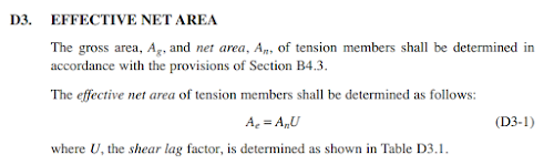
Due to the behavior of shear lag, the effective area of the tension member is getting reduces. So, this reduction in the area is applied in the form of “shear lag factor, ‘U’” in AISC-360-10/16.
Herewith attached the snap from AISC-360-10 to determine the effective area and the table to determine the shear lag factor for different cross-sections.
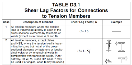
The shear lag factor can be determined based on case 2 of the table. As we closely look, the factor depends on two things, firstly the centroidal distance from the plane of connection, secondly the length of the connection.
So, if we are about to increase the effective area (which would ultimately increase the tensile capacity of the section), we should try to reduce the value of ‘x’ (centroidal distance from connection plane) and increase the length of the connection.
Keeping the concepts that we learned so far in front, let me ask you a question.
If you are using an unequal angle section (one leg will be longer than the other), which leg will u connect in order to get higher tensile capacity?
Obviously, the longer leg. Why do we do so? Because it will considerably reduce the value of “x” considering the short leg being connected.
In IS-800:2007, we do follow the following steps to determine the tension capacity of the section.
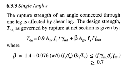
What is happening in the above formula, the capacity of the connected leg and outstanding leg are separately calculated. The assumption here is that the outstanding leg will reach yielding stress when the connected leg probably would have attained the ultimate stress.
The net area is calculated for the connected leg to determine its capacity. The area of the outstanding leg is reduced with the reduction factor “β“, which is our shear lag factor. It depends on the factors like the length (L) of the connection and shear lag width (bs).
Alternatively, a simpler approach is also provided in IS-800:2007 as shown in the snap below.
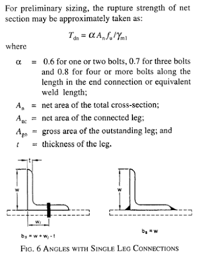
Here, the net sectional area is multiplied with the reduction factor “α” to account for the shear lag based on the number of bolts used in the connection (Length of the connection).
Inference/Conclusion
As we have seen the concept of shear lag and the factors affecting it, the following are my inference
- The thickness of the member does not play a role in the determination of shear lag factor or it does not affect the tensile capacity of the section.
- If the distance between the plane of connection and the centroidal axis of the outstanding leg increases, it reduces the tension capacity of the section.
- From the experimental studies, it is proved that if the length of the connection is increased up to 4 bolts, the tensile capacity increases. And if we further increase the length it does not have a significant effect. (Kulak and Wu, 1997).
Also check out my YouTube Channel: Structures Simplified
2 thoughts on “Shear Lag in Steel Structures”
Applauses to this detailed explanation
Thank you