
If you are a professional design engineer, then most probably you would have heard about this particular collapse dated a few decades back.
July 17, 1981, is an unforgettable date similar to 9/11. One of the deadliest structural failure recorded in American history which took place in the city of Kansas, Missouri.
Yes, I am talking about the Hyatt Regency hotel walkway collapse.
But, WHY?
Why this particular collapse?
Why it is so important?
If someone wants to understand that simple misunderstanding can cause severe collapse, then they should definitely go through the failure study of the Hyatt Regency walkway collapse.
Let me depict the story first, and we see the structural aspect of it after.
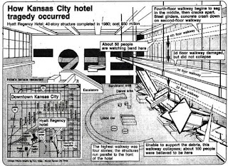
So, it goes like this. The hotel was opened to the public by 01-July-1980. Exactly one year and 17 days later from its inaugural, there was a huge gathering in the evening of 17-July-1981, for a tea dance in the atrium, and that is when the tragic event occurred.
There were three walkways that connect the north and south wing of the hotel. The fourth-floor walkway lies just above the second-floor walkway and the third-floor walkway runs at some offset from these two. (shown in the figure below)

Why did it happen?
The main reason for the collapse is stated as the mismatch between the original design and the one which has been executed.
Moving to the structural aspects:
The original design of the walkway incorporates a steel hanger that supports the two floors of walkways, fourth floor lying above the second floor.
The floor is supported over the cross beams and these cross beams are inturn were hanged from the ceiling with the help of hanger rods and nuts. One important detail to note is that this hanger rod supports two walkways. As per the original design, in order to support the fourth-floor walkway, the nut has to be screwed from the bottom (i.e. from the second floor) up to the fourth floor. The entire hanger rod between the fourth and second floors needs to be threaded.

This simple change from the steel manufacturer affected the whole design leading to the collapse of walkway.
This change had doubled the load that comes to the fourth-floor cross beam.

As we see detail 1, it is very clear that the cross beam is supported by the nut. Say, if the floor load is “P”, then the hanger rod on each side would experience a force of “P/2”.
Now, look into detail 2, there is a rod that is supporting the second floor gets attached to the cross beam on the fourth floor. So, the load from the second floor gets transferred to the cross beam in the fourth-floor through the hanger rod. Considering the load on second floor as “P” and since there is a hanger on two ends, each hanger would transfer a force of “P/2″ to the fourth floor. There is already a floor load of “P/2” on one side of the hanger that would be due to the fourth-floor load.
Summing up the entire loads acting on hanger at the fourth floor gives (P/2 + P/2) = “P” (For the original design, it was P/2).
This change in load path was the major issue which is not addressed during the revision..
Original Load path: Floor – Cross beam – Steel hanger rods (both floors have a similar load path)
Revised Load Path: Second floor – Cross beam on second floor – steel hangers – Cross beam on Fourth floor – steel hangers.
This is where the loads get doubled.
What will happen to the structural components because of this increased load?
The nut which holds the beam in place won’t fail easily, similarly the force on hanger rod as per the original design and the modified one is same since it has to carry loads of both the floors in two cases, it won’t fail.
The only element which is susceptible to be affected by this change is the cross beam on the fourth floor, upon which double the times of actual design load is about to act.
One more amplifying factor is that the cross beam is a built-up box which is made from two C-sections that are welded face to face throughout its length. The hanger rod passes through the plane of a weld (which is the weakest portion in the build-up member) which resonated the speed of collapse.
Final takeaway – If not properly addressed, shifting the orientation of a single rod in design could result in a catastrophic failure.
Also check out my YouTube Channel: Structures Simplified