
During the initial stage of one’s career, every design engineer, especially a steel design engineer would have come across this statement “Bending force is carried by the flange of an I-Section, and shear force is taken care of by the web“.
Like everyone, when I first heard this, just started to keep this as a thumb rule and practice it.
Never asked a question ” WHY..? ”
Until someone else asked me, why we consider shear is taken by the web of an I-Section.
This article is about that question.
And this question can be answered in one simple sentence, as well as it can be discussed elaborately like a research article.
I just want to make it as simple as possible with sufficient explanation. With this in our mind, let’s get into it.
Why webs carry all the shear?
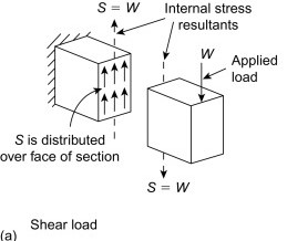
Due to the applied transverse load on the beam, internal forces parallel and opposite to the applied load will be generated along the beam cross-section. This force is called “Shear Force”, which has the effect of shearing away the cross-section.

The best example for a shear force is scissors, just imagine you are cutting cardboard with the help of scissors, the two blades of the scissors must employ force parallel and opposite to each other along the cross-section of the cardboard in order to tear it off.
As we already know, though we have shear force, we need shear stress to determine the shear capacity of the member. (This topic is already discussed in the blog)
Now, we are about to determine the shear stress distribution for an I-section. Once, we have the shear stress distribution, we can clearly understand why we consider the web is subjected to shear rather than the flange.
We could easily find a formula to determine the shear stress distribution along the cross-section from any strength of materials or statics book.
The shear stress, τ is given as
τ = VQ/ Ib
Where V = The shear force
Q = The first moment of area
I = Moment of Inertia of the cross-section
b = Width of the cross-section at the point of interest
If we observe the above equation, we could easily determine, which are the factors that influence the shear stress along the cross-section of a member.
The first parameter, V does not vary, since it is the shear force, it remains the same throughout the cross-section. Secondly, the “I” moment of inertia of the cross-section is also a constant for a particular cross-section.
The parameters, “Q” and “b”, are the variables in the above equation, which determines the distribution of shear stress. Of these two, let’s not worry about “Q” the first moment of area for a while. Let’s concentrate on “b” the width of the cross-section.

From the cross-sectional image, consider we are determining the shear stress at point A, the width “b” is the entire breadth of the flange. Whereas, if we move to point B, it is just the thickness of the web.
Comparing the parameter “b” at point A and B, we could easily realize that at point A, the “b” value will be more. If we have a higher “b” value in the formula of shear stress, then obviously it would result in the least shear stress. And as the value of “b” is getting decreased, the shear stress increases.
Now, let’s look into the “Q”, the first moment of area. It is proved from the name of the parameter that as the area increases, the value of Q also increases. So, starting from the top and moving towards the neutral axis, the area is getting increased, which leads to an increase in Q value.
Plotting the value of shear stress distribution along the cross-section would result in the diagram as shown below.
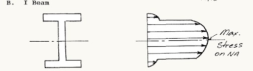
As we can see, the shear stress is zero initially at the top, and as we move down the top flange, the “b” value will be constant, but the “Q” value will be increasing, resulting in the parabolic curve. As soon as we reach the web part, because of decrease in “b” value, there is a sudden increase in the shear stress and as we move further, the “b” value remains constant, the parabolic increase in the value of shear stress is due to the increase in the first moment of area “Q”, reaching the maximum stress at the neutral axis.
CONCLUSION
As we can see visually from the shear stress distribution, the flange does have very little shear stress distributed compared to the web portion. For this reason, we designers follow the thumb rule that “web will carry all the shear”.
Also check out my YouTube Channel: Structures Simplified
Similar Articles: