What is the importance of employing Lx, Ly & Lz for a member during the design stage?
Every structural or civil engineer would be aware of column buckling behavior. Which is one of the predominant failure modes for the column, especially for a long column.
There will be this famous statement, “doubling the length of the column, reduces the load-carrying capacity of the column by the factor of 4“.
Also, the effect of end conditions on the buckling strength will be strongly emphasized in each of our design classrooms.
The effective length factor (K) of the column varies with different boundary conditions, say for pinned-pinned boundary condition, it is “1”. And for other boundary conditions, it varies respective to the distance between the point of inflection, approximating the pinned-pinned end condition. Hope you guys are aware of these details, if not kindly try to gain some insight as they are very basic concepts.
In general, everyone has some ideas on effective length and effective length factors. Now, let’s move to the design aspect.
Say, I have decided to design a column of 5m length for a concentrated load of 100kN. Let’s consider, after the design process, I am arriving at the ISMB300 section.
I am giving that section for approval, and the end-user rejects that section, saying they can’t go for the ISMB300 section at that location, due to some site constraints, and they are asking to reduce the section depth.
In that scenario, as a design engineer what would you do?
You have two choices,
- Asking the client to shift the location of the column.
- Reducing the section as per client request.
How do we do that?
– By introducing “Intermediate Restraints“.
As we see already, the predominant mode of failure, in this case, is buckling. What if we reduce the effective length of the member by providing a brace or lateral restraint to prevent it from buckling at the center. The effective length of the member would be reduced to half, which will increase the load-carrying capacity by the factor of 4. Is not it?
So, the best solution is to brace our column. Then there pop-outs the next question.
Which direction should we brace?
If we consider an I-section, there are two axes, namely the major axis and minor axis. As we know, the buckling load depends on the slenderness ratio of the member. We have to brace the axis which has the least slenderness ratio.
Providing the brace along the major axis is merely useful to nothing. So, we should go for providing intermediate restraint along the minor axis.
How do we incorporate this intermediate bracing in the design?
In the site condition, we can manage to provide a strut tube or secondary beam connecting the minor axis to another column or support. In a 2D design platform, to incorporate this effective length concept, there are parameters like Lx, Ly, and Lz in software packages like STAAD Pro.
They are nothing but the effective length of the member. Once we assign proper value for Lx, Ly, and Lz it replicates the actual condition by considering that length for the determination of column buckling load.
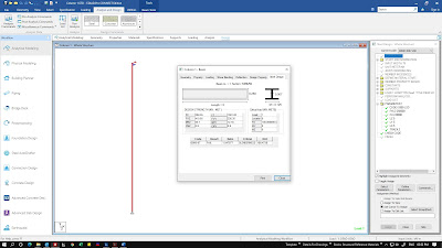
Herewith attached the sample snap of the STAAD environment, where I modeled the column with full effective length and half effective length. Just look at the column buckling load capacity.
 |
| Fully Unsupported Column |
 |
| Braced at Mid Height |
 |
| Typical Pre-Engineered Building Cross-Section |
How do we determine the effective length for the rafter and column sections?
CONCLUSION:
A simple trick to arrive at the effective length for any member is that, if we are about to determine the effective length for the major axis (Lz) of the member, then we should look whether there are any supporting members running parallel to the other axes (X & Y axes).
Feel free to ask doubts in the comment section.


One thought on “How to apply the effective length of a member in the design process?”
Yes. It is. A column in the typical PEB will be supported at ground and at top with rafters, there wont be any restraint in-between. So, the effective length along major axis will be the length of the member in most cases. If there is a mezzanine floor or multiple levels of mezzanine, there will be restraint in both the directions due to mezzanine joist and beam arrangements, in that case, effective length along major axis can be taken as the unsupported length between the mezzanine levels.